The MSU Cube Sat Program
ABSTRACT
The Electronic Engineer Faculty of Buenos Aires University in currently cooperating with Universidad Tecnologica Nacional and the Argentine amateur satellite community in a full scale development of a new cubesat initiative . Know as the MSU-1 (micro satelite universitario), program, the project’s goal is to produce student engineered satellite capable.
ObjetivEs OF THE MISSION
- Test two passive control techniques: gravity-gradient and aerodynamic.
- Amateur Digipeater communication at 2m band .
- Send telemetry to the ground station upon request.
- Verify the reliability of the subsystems.

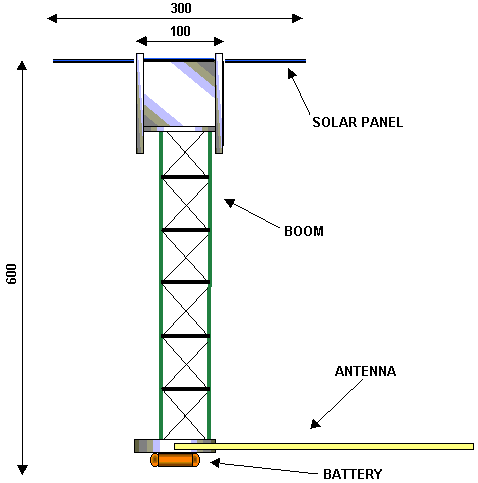
Figure 1 –
MSU-01 Orbit Configuration (boom, solar panels and antennas deployed)
STRUCTURE
- Provide mechanical support and mounting for all other spacecraft subsystems, equipment hardware and accessories.
- Avoid coupling of the spacecraft vibration modes with those of the launch vehicle, as well as to provide resistance to its static and dynamic launching environment
- Provide sufficient dynamic impedance to avoid exceeding the equipment specified vibration levels.
- Provide the mechanical means for solar panels restrain release, deployment and lock and antenna arrays.
- Provide the satellite mechanical interface with the launch vehicle.
- Provide support for the static and dynamic balance adjustable masses of the integrated spacecraft.
CONFIGURATION
10 cm side cube (launch configuration) and total mass of 1 Kg.
Standard aluminum alloy materials and corresponding well known manufacturing processes.Components : 4 lateral panels, a top platform and the boom platform.
ON BOARD CONTROL SUBSYSTEM
Terminal node controller (TNC)
- Receives and transmits information
- Protocol: packet radio AX25.
- Hardware: Microcontroller PIC16FC84 and a modem.
- Transmission rate of 1200 baud for packets up to 32 bytes each.
Telemetry
- Developed at independent board.
- 5 analog inputs and 8 digital outputs.
Variables sampled:
- Temperature sensing (-30ºC to 80ºC)
- Current ( 0 to 500mA ),
- Battery voltage ( 3V to 12V)
- Transmission power
Deploy and Command Unit
- Deploy the BOOM
- Deploy the solar panels
- Deploy the antenna
- Process commands from earth
COMUNICATION SUBSYSTEM
AFSK Transmitter
- Digital discrete on board transmitter working in the radio amateur 2m band (145.81MHZ).
- Constructed with discrete components to increase reliability and reduce power consumption.
- Input signal: binary baseband signal (2 tones of 1200 and 2400Hz).
- Power delivery in ON mode is approximately 150mW
- Power consumption On Mode: 400mW
- Power consumption Sleep Mode: <10mW
- On/off-input signal disables the power stage of the transmitter.
- Power supply from 6Volts DC.
- Transmission rate of the information: 1200 BPS

Fig.3 Transmitter module
FSK Transmitter module is divided as:
Low power Colppits oscillator, mixer and frequency multiplier amplifier stages.
Power Stage Class C amplifier.
Antennas System
Two monopoles of metallic strip of (/4, one for the transmitter and another for the receiver.
Receiver
Constructed with CI at frequency of 145.990 MHz.
Power Subsystem
- 7 AAA batteries of Ni-Cd.
- Five Solar Panels.
Back to Return


